Important
SymbiFlow is now F4PGA. See f4pga.org, f4pga.readthedocs.io and f4pga-examples.readthedocs.io.
Building example designs
Before building any example, set the installation directory to match what you set it to earlier, for example:
export INSTALL_DIR=~/opt/f4pga
Select your FPGA family:
FPGA_FAM="xc7"
FPGA_FAM="eos-s3"
Next, prepare the environment:
export PATH="$INSTALL_DIR/$FPGA_FAM/install/bin:$PATH";
source "$INSTALL_DIR/$FPGA_FAM/conda/etc/profile.d/conda.sh"
export PATH="$INSTALL_DIR/$FPGA_FAM/quicklogic-arch-defs/bin:$PATH";
source "$INSTALL_DIR/$FPGA_FAM/conda/etc/profile.d/conda.sh"
Finally, enter your working Conda environment:
conda activate $FPGA_FAM
Tip
You will need to run the commands for setting the path and source of your conda environment
each time you open a new terminal. You will also need to activate the Conda environment for
your hardware before you attempt to build your designs. It might be a good idea to add the
above commands to your .bashrc either as default commands that run each time you open a
new terminal or aliases to save yourself some repetitive typing.
Note
If you don’t know how to upload any of the following examples onto your development board, please refer to the Running examples section.
Note
Make sure you have executed all the above commands, or otherwise you may encounter errors when building the designs.
Xilinx 7-Series
Enter the directory that contains examples for Xilinx 7-Series FPGAs:
cd xc7
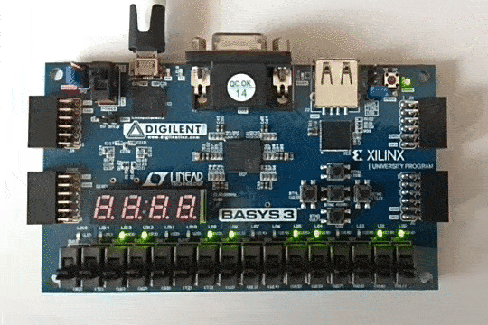
Counter test
This example design features a simple 4-bit counter driving LEDs. To build the counter example, depending on your hardware, run:
TARGET="arty_35" make -C counter_test
TARGET="arty_100" make -C counter_test
TARGET="nexys4ddr" make -C counter_test
TARGET="basys3" make -C counter_test
TARGET="nexys_video" make -C counter_test
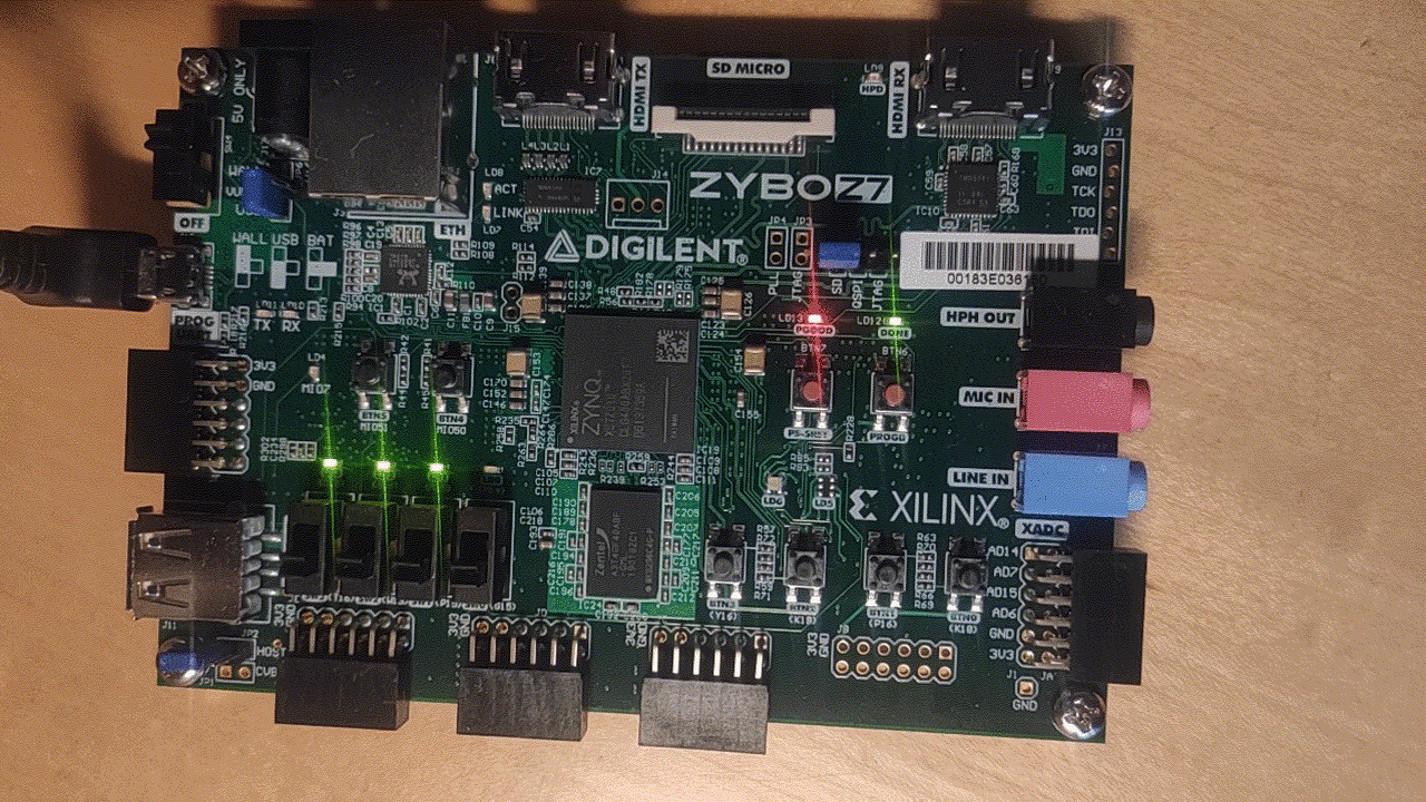
TARGET="zybo" make -C counter_test
At completion, the bitstreams are located in the build directory:
counter_test/build/<board>
Now, for Arty and Basys3, you can upload the design with:
TARGET="<board type>" make download -C counter_test
The result should be as follows:
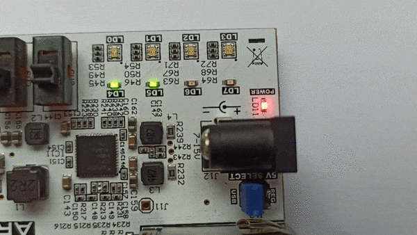
For Zybo, please follow the guide on how to load a bitstream from U-boot.
Once the bitstream is loaded, the result should be as follows:
On the picocom terminal, you can control the counter behaviour to stop it, or let it count backwards, by toggling values of the EMIO pins of the ARM Processing System (PS).
You can control the counter enable signal with:
gpio set 54
gpio clear 54
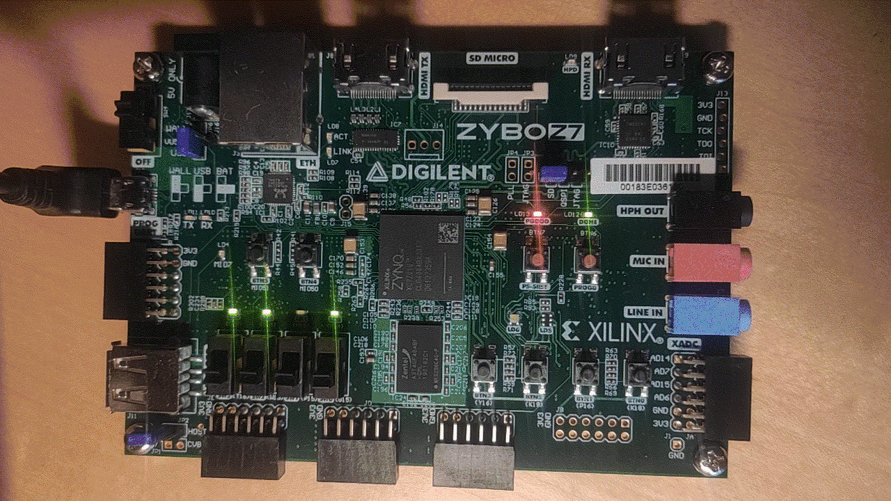
If GPIO 54 is set, the counter is disabled. It is enabled if the GPIO 54 is cleared. The result should be as follows:
You can control the counter direction with:
gpio set 55
gpio clear 55
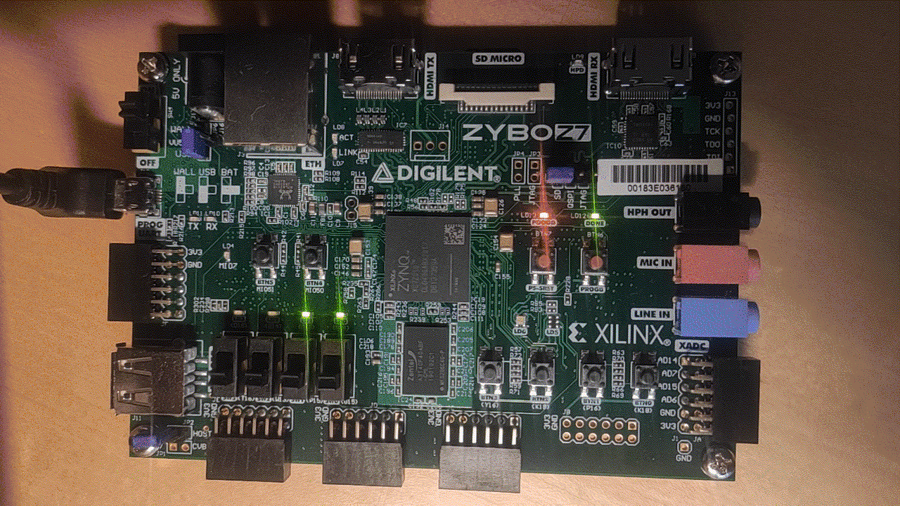
If GPIO 55 is set, the counter goes backwards. It goes forwared if the GPIO 54 is cleared. The result should be as follows:
PicoSoC demo
This example features a picorv32 soft CPU and a SoC based on it. To build the picosoc example, first navigate to the directory that contains examples for Xilinx 7-Series FPGAs. Then run the following commands:
TARGET="arty_35" make -C picosoc_demo
TARGET="arty_100" make -C picosoc_demo
TARGET="nexys4ddr" make -C picosoc_demo
TARGET="basys3" make -C picosoc_demo
At completion, the bitstreams are located in the build directory:
cd picosoc_demo/build/<board>
Now you can upload the design with:
TARGET="<board type>" make download -C picosoc_demo
You should observe the following line in the OpenOCD output:
Info : JTAG tap: xc7.tap tap/device found: 0x0362d093 (mfg: 0x049 (Xilinx), part: 0x362d, ver: 0x0)
The UART output should look as follows:
Terminal ready
Press ENTER to continue..
Press ENTER to continue..
Press ENTER to continue..
Press ENTER to continue..

 ____  _          ____         ____
|  _ \(_) ___ ___/ ___|  ___  / ___|
| |_) | |/ __/ _ \___ \ / _ \| |
|  __/| | (_| (_) |__) | (_) | |___
|_|   |_|\___\___/____/ \___/ \____|


[9] Run simplistic benchmark

Command>
Note
PicoSoC uses baud rate of 460800 by default.
The board’s LED should blink at a regular rate from left to the right
LiteX demo
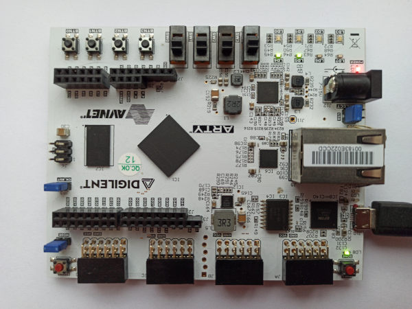
This example design features a LiteX+<CPU variant>-based SoC. It also includes DDR controller. First, enter this example’s directory:
cd litex_demo
Install the litex dependencies with the following:
pip install -r requirements.txt
There are multiple CPU types supported, choose one from the below commands to generate the design and build it.
Picorv32
./src/litex/litex/boards/targets/arty.py --toolchain=symbiflow --cpu-type=picorv32 --sys-clk-freq 80e6 --output-dir build/picorv32/arty_35 --variant a7-35 --build
./src/litex/litex/boards/targets/arty.py --toolchain=symbiflow --cpu-type=picorv32 --sys-clk-freq 80e6 --output-dir build/picorv32/arty_100 --variant a7-100 --build
VexRiscv
./src/litex/litex/boards/targets/arty.py --toolchain=symbiflow --cpu-type=vexriscv --sys-clk-freq 80e6 --output-dir build/vexriscv/arty_35 --variant a7-35 --build
./src/litex/litex/boards/targets/arty.py --toolchain=symbiflow --cpu-type=vexriscv --sys-clk-freq 80e6 --output-dir build/vexriscv/arty_100 --variant a7-100 --build
Depending on which board and CPU-type you selected, the bitstream is loacted in:
cd build/<cpu-type>/<board>/gateware
Now you can upload the design with:
openocd -f ${INSTALL_DIR}/${FPGA_FAM}/conda/envs/${FPGA_FAM}/share/openocd/scripts/board/digilent_arty.cfg -c "init; pld load 0 top.bit; exit"
Note
This example uses baud rate of 115200 by default.
You should observe the following line in the OpenOCD output
Info : JTAG tap: xc7.tap tap/device found: 0x0362d093 (mfg: 0x049 (Xilinx), part: 0x362d, ver: 0x0)
In the picocom terminal, you should observe the following output:
Linux LiteX demo
This example design features a Linux-capable SoC based around VexRiscv soft CPU. It also includes DDR and Ethernet controllers. To build the litex example, run the following commands:
To build the linux-litex-demo example, first re-navigate to the directory that contains examples for Xilinx 7-Series FPGAs. Then, depending on your hardware, run:
TARGET="arty_35" make -C linux_litex_demo
TARGET="arty_100" make -C linux_litex_demo
At completion, the bitstreams are located in the build directory:
linux_litex_demo/build/<board>
Now you can upload the design with:
TARGET="<board type>" make download -C linux_litex_demo
Note
You may find these information useful to correctly setup the network interface: timvideos/litex-buildenv/wiki/Networking.
You should observe the following line in the OpenOCD output:
Info : JTAG tap: xc7.tap tap/device found: 0x0362d093 (mfg: 0x049 (Xilinx), part: 0x362d, ver: 0x0)
In the picocom terminal, you should observe the following output:
Additionally, two LED’s on the board should be turned on
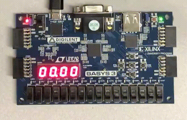
Timer
This example is built specifically for the basys3 and demonstrates a greater variety of I/O then previous designs. It also demonstrates F4PGA’s support for code written in System Verilog as well as its support of dictionaries in XDCs. To build this example run the following commands:
make -C timer
At completion, the bitstream is located in the build directory:
timer/build/basys3
Now, you can upload the design with:
TARGET="basys3" make download -C timer
After downloading the bitstream you can start and stop the watch by toggling switch 0 on the board. Press the center button to reset the counter. The following gives a visual example:
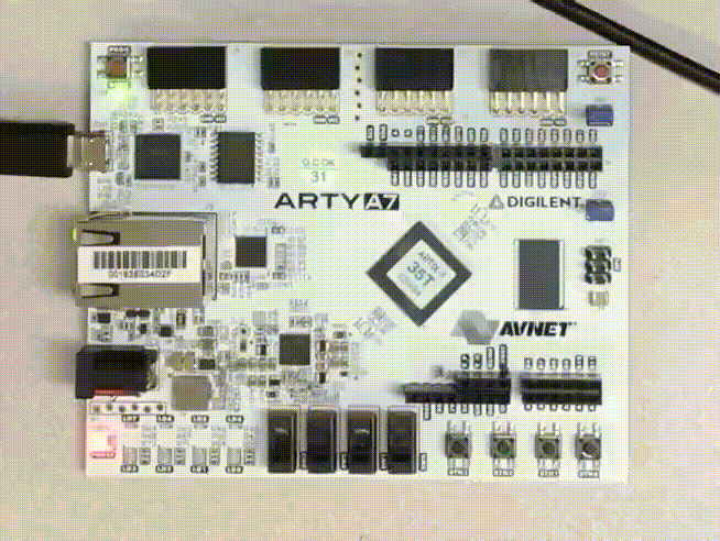
Pulse Width
This example is built specificity for the arty_35T. It demonstrates a greater variety of I/O and a PWM that drives the RGB leds on the board. To build this example run the following commands:
make -C pulse_width_led
At completion, the bitstreams are located in the build directory:
pulse_width_led/build/arty_35
Now, you can upload the design with:
TARGET="arty_35" make download -C pulse_width_led
After downloading the bitstream, you can experiment with and mix different amounts of red, green, and blue on RGB led 0 by toggling different switches and buttons on and off. From left to right: switches 3, 2, 1 control the intensity of blue, switch 0 and buttons 3 and 2 control the intensity of red, and buttons 1 and 0 control the intensity of green. The following provides an example:
QuickLogic EOS S3
Enter the directory that contains examples for QuickLogic EOS S3:
cd eos-s3